+86-173-0318-1768
- All
- Product Name
- Product Keyword
- Product Model
- Product Summary
- Product Description
- Multi Field Search

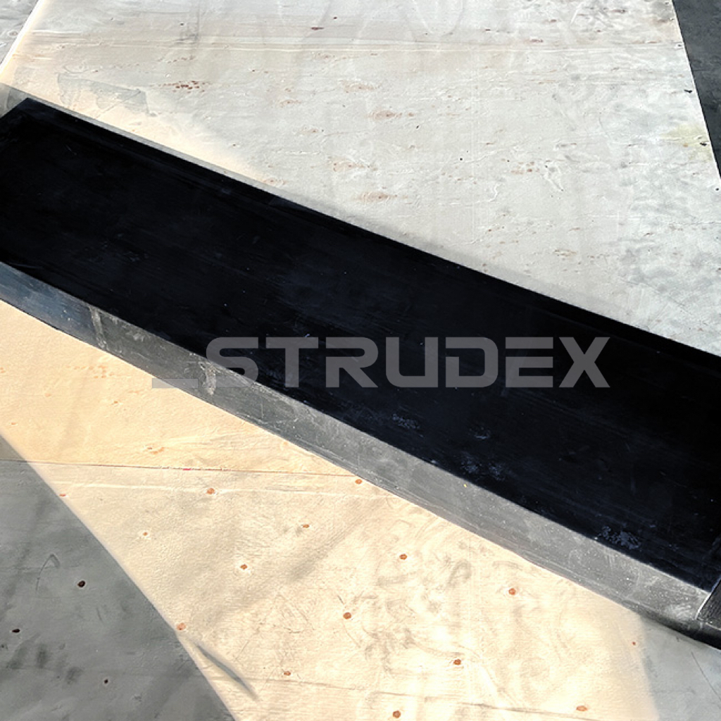 |


Strudex screening side-wall liners provide abrasion-resistant rubber protection with a listed thickness range of 5–50 mm. Bolt-on and selected snap-on designs offer different retention interfaces. Choosing a section means balancing wear material, deck clearance and the levels of neighboring liners.
Treat thickness and mounting as linked choices. A thicker section needs room to work, and a different fixing profile needs a matching support rather than only the same panel outline.
| Quantity: | |
|---|---|
Strudex rubber side-wall liners offer a listed 5–50 mm thickness range for protecting screening-machine side panels. The available configurations include bolt-on and selected snap-on designs. These choices define a complete section against the wall: rubber thickness supplies wear material, while the retention interface and adjoining edges determine how that material can be installed and kept in its intended position.
| Parameter | Product specification |
|---|---|
| Product type | Screening side-wall liner |
| Material | Abrasion-resistant rubber |
| Listed thickness range | 5–50 mm |
| Thickness configuration | Custom thickness requirements reviewed by application |
| Mounting configurations | Bolt-on; snap-on for selected designs |
| Lining configuration | Standard and custom arrangements |
| Equipment application | Vibrating screens and industrial screening machines |
| Industry applications | Mining, quarrying, recycling and aggregate processing |
A thicker side liner adds rubber between the material stream and the metal wall. It also moves the working face inward. That change can reduce available clearance at the deck edge, alter the step to a neighboring liner and affect access to clamps or fixings. The appropriate thickness therefore follows the local wear duty and the assembled geometry, not an assumption that the largest listed section is always preferable.
| Choice | Potential value | Interface to check |
|---|---|---|
| Repeat the existing new thickness | Preserves the original envelope when the previous geometry and material duty remain suitable. | Use original new dimensions. A worn sample may have lost enough section to conceal how the assembly originally fitted. |
| Increase thickness in a high-wear area | Places additional wear material at a defined contact location. | Compare the inward projection with deck clearance, feed path and retained liner levels. Show the edge transition on the drawing. |
| Use a different thickness along the wall | Allows separate contact zones to be considered on their own duty. | Coordinate junctions so a new projection does not become an exposed leading edge or leave a route behind the protection. |
| Change the mounting configuration | May address a specific installation or removal requirement when a matching system is selected. | The receiving profile, engagement and support must suit the new design. Thickness and outline alone do not establish that conversion. |
A side panel can see impact near the feed entrance and progressive sliding wear alongside the material bed. At a joint or a change in wall angle, an edge may receive a concentrated load. Identify which of these conditions consumes the section. A local torn corner and a broad worn track can call for different geometry reviews even when the measured minimum thickness is similar.
| Observed condition | Replacement implication |
|---|---|
| One position wears through first | Locate the feed landing point and contact path. Determine whether the loading is concentrated or whether the panel has lost support before selecting a heavier set for the whole wall. |
| A fixing or retention region is damaged | Assess the mating parts and the supporting wall. The usable face thickness cannot compensate for an attachment that no longer retains the liner as designed. |
| A new section meets an older thin section | Check the resulting step and the direction of material travel. The retained profile may control whether a partial replacement forms a suitable boundary. |
| Material accumulates along the wall | Separate adhesion, restricted clearance and uneven loading. A change in rubber thickness is not an independent cure for a feeding or material-condition problem. |
| Replacement route | Geometric and functional requirement |
|---|---|
| Dimensional repeat | For a dimensional repeat, confirm the current drawing and the retained mounting system. Check whether the same wear mechanism ended the previous campaign. A repeat can be appropriate when the geometry remains suitable, rather than changing the section simply because another thickness is available. |
| Thickness change | For a thickness change, show the present and proposed profiles together with deck level and adjacent parts. Identify the region receiving the added material and the effect on the passage. This makes the proposal a defined geometric change rather than only a new millimeter value. |
| Mounting change | For a mounting change, define the complete receiving interface and its support. State which components remain, which change and the intended removal access. An approved connection is required before a bolt-on section can be replaced by a snap-on one. |
Rubber selection also depends on sharp contaminants, temperature and chemical exposure. The wear-resistant material description does not establish a universal operating limit. Include those exposures in the proposed section, particularly where cutting or swelling differs from ordinary abrasion. Inspect the metal wall separately if it is already cracked or deformed.
A useful Strudex specification names the thickness, outline, wall position and mounting configuration as one component. Include the neighboring liner levels and the actual contact zone. This keeps the 5–50 mm range useful as a selection range while avoiding an unsupported promise that every listed section fits every screen.


